| 1: Introduction |
|
This is a starter guide to operating the Comet 4. As usual it's aimed at the novice, so please don't be insulted if you know all the basics.
Again slightly different to previous guides (VC10 & 1-11), this one is a simple run through the checklists incorporating the before starting, starting, taxi, takeoff, after takeoff, climb & cruise, descent, approach, final, after landing and shutdown checks.
The guide is made from the VC, but it will still be of use to 2D panel users.
Also take a good look through the Comet Manual to get the most out of the model.
|
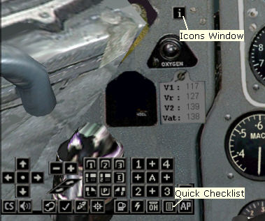 |
The panel has a number of icon buttons grouped on a popup window.
This popup window is toggled on & off by clicking on the icon button 
Clicking the 'checklist' icon  brings up the Comet 4 checklists booklet. brings up the Comet 4 checklists booklet.
Click the preset views - 3 overhead, 2 forward, Engineer, Left Window, Right Window & Pedestal to see all the useful sections of the VC.
|
|
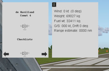 |
Page through the booklet by clicking on the arrows at the bottom of the page.
The extra data sheet on the right can be toggled on & off by clicking the icon in its top left corner.
Please be aware that the items in this guide may change slightly over time as the model develops. |
|
The model will be loaded into FS with all systems running.
Once the model is fully loaded into the sim, so long as you are stationary, you can click the 'cold start'  icon to shut everything down. This guide assumes you are starting from cold. icon to shut everything down. This guide assumes you are starting from cold.
Note that the first 8 seconds after the model is loaded is an initialization period. Any clicks you do during this time may well be ignored.
|
|
| 2: Before Starting |
 |
|
| |
|
| Battery (or External Power) |
ON |
 |
The model has no real link to external power.
The external power setting is only pretend & actually uses the FS battery.
Because of this there is still a time limit before the power runs out when external power is selected.
Once the engines are started, battery power is no longer used. |
| |
|
| Invertors |
ON |
 |
| The invertors convert DC power to provide AC power to various instruments. |
| |
|
| Parking Brake |
ON |
 |
| |
| |
|
| Nav Lights |
ON |
 |
| Beacon |
ON |
Either knob on the left can be clicked to turn on the VC roof lights. Can be useful during day time as it can still get a little dark in a VC.
If the beacon causes the VC roof lighting to flash, turn the VC lights off & turn them back on again.
The other switches on this panel are only dummy switches. |
| |
|
| Fuel Cocks |
ON |
 |
The model uses a simplified left / centre / right arrangement for the fuel system.
All left tank cocks operate together, same with the right. |
| |
|
| Wing Fuel Pumps |
ON |
 |
All of the left & right tanks are in the wings.
Similar to the fuel cocks, all left fuel pumps operate together, same with the right pumps.
On the Comet the fuel pumps are used to bring the tanks in and out of the fuel system, never the fuel cocks.
The fuel cocks are always OPEN unless the fuel tank is empty, in which case the fuel cock must be closed.
On the model, when fuel pumps are off, fuel can not be delivered from that tank. |
| |
|
| Centre Fuel Pumps |
OFF |
 |
The lines on the schematic show how the fuel tanks link to the four engines, with the round 'gulls eye' indicators either linking or breaking the connections.
Note that the centre tank is naturally routed to only feed the left two engines. It will only ever feed the right side if the crossfeed is opened.
The three crossfeeds are represented with three 'gulls eye' indicators between the fuel flow gauges at the top. |
| |
|
| Fuel Crossfeeds |
CLOSED |
 |
| With the centre pumps off and the crossfeeds closed, the engines are being fed direct from their respective wing fuel tanks. |
| |
|
| Fuel Heaters |
As Required |
 |
If the temperature is below 5 deg C, fuel heaters would be required.
Fuel inlet temperature is shown by the gauges above the switches. |
| |
|
| Starter Master Switch |
ON |
 |
| No engines can be started without the Starter Master Switch being on. |
| |
|
|
|
| 3: Starting |
 |
|
| |
| Repeat for each engine |
| Select Engine |
(1,2,3,4) |
 |
This is a four way rotary switch 1,2,3,4.
Each click with the mouse advances it to the next engine.
Clicking when on engine 4 returns it to engine 1. |
| |
|
| LP Cock |
ON |
 |
| |
| |
|
| HP Cock |
ON |
 |
| On the Comet the HP cock is fully on before ignition. |
| |
|
| Starter Button |
PRESS |
 |
Once pressed, the starter button stays down until the start sequence is complete to ignition or not.
Each engine has a generator which should automatically come on line as the engine starts.
If the engine fails to light and reach idle RPM, wait until it has wound down (check RPM gauge) and press the engine starter button again.
If the generator is not active, it will need to be reset on the engineers electrical panel (there are 4 generator buttons behind red guards) |
| |
|
| All Engines |
Running |
|
| Only proceed once all engines are running. |
| |
|
| Starter Master Switch |
OFF |
 |
| |
| |
|
| Pressure Supply Levers |
ON |
 |
Each engine provides air to the pressurization & heating system.
This air is only provided at RPMs well above Idle. If heating is needed on the ground, set engine RPMs up until the cabin mass flow gauges (on the pressurization panel) register more than 1. |
| |
|
| De-ice Levers |
As Required |
 |
If it was cold, de-ice would be required.
These levers provide structural de-icing of leading edges etc. |
| |
|
| Engine De-ice |
As Required |
 |
| If it was cold, engine de-ice would be required. |
| |
|
| External Power |
OFF |
 |
Once the engines are going, battery & or external power is not needed.
If external power was selected it should be deselected before taxi. |
| |
|
|
|
|
|
| 5: Takeoff |
 |
|
| |
|
| Pitot Heat |
ON |
 |
| Keeps the pitot tubes clear of ice & so ensures that the IAS indicator keeps working. |
| |
|
| Reverse Lock |
ON |
 |
Reverse lock blocks selection of reverse thrust.
This lever is only available in the VC. In FS there is no real disadvantage in ignoring it.
The Comet had it because reverse thrust was selected by pulling the outer throttles back beyond the idle position. |
| |
|
| Autopilot Master |
ON |
 |
| Autopilot |
DISENGAGED |
Autopilot can not be powered up without Autopilot Master being switched on.
And there is a double check that the A/P is not somehow engaged. |
| |
|
| Landing Lamps |
ON |
 |
| |
| |
|
| Top Temp Control |
ON |
 |
Top Temp monitors the engines & will automatically reduce power to keep them within set limits.
It is impossible to overheat the engines with Top Temp on. |
| |
|
| Relight Override |
ON |
 |
Sets all engines to automatically attempt a relight in the event of an engine stopping.
|
| |
|
| Engine Synchronizer |
OFF |
 |
The engine synchronizer forces other engines to adopt the same RPM as the nominated engine (usually no 1 engine 'Port Outer').
All engine control must be independant for takeoff. |
| |
|
| Power |
FULL |
 |
| Brakes |
OFF |
Full power should give around 8000 - 8150 RPM depending on the conditions.
Rolling start or hold with pedal brakes is ok. |
| |
|
Calls will come for V1 and Rotate (Vr).
At rotate gently pull back the yoke & lift off.
The Comet can climb steeply even when at full weight.
It was quite normal to adopt an initial climb speed of only 150 kt, gaining height quickly to help with noise abatement.
Acceleration is rapid & so the yoke needs to be held back to keep to 150 kt.
Adjust elevator trim if needed. |
| |
|
|
|
| 6: After Takeoff |
 |
|
| |
|
| Gear |
UP |
 |
| In the VC this lever needs to be dragged, rather than just a single click. |
| |
|
| Yaw Damper |
ON |
 |
This gauge is on the co-pilot side & is only available in the VC.
There's no great need to set it on in FS. |
| |
|
| Flaps |
UP at 1500 ft |
 |
Once the flaps are up you will need to lower the nose & get some speed up.
Some elevator trim adjustment is usually required.
The large wing creates a fair amount of drag at higher angles of incidence, so keep a positive acceleration up to your climb speed. |
| |
|
| Landing Lamps |
OFF |
 |
| No great rush, as there's no damaging speed to worry about for the lights since they are all flush fitted into the wing. |
| |
|
| Cabin Alt |
Check Rising |
 |
Make sure pressurization is working properly, the rate should normally rise at 400 ft per minute until the cabin height has reached the set required level.
The rate can be selected using the knob at the top left of the gauge. |
| |
|
| Climb Power |
7400 RPM |
 |
| Max continuous engine temperature is 570 deg C, but up to 650 is allowed for 5 mins. |
| |
|
| Autopilot |
POWER ON |
 |
The A/P will take about 45 seconds to power up.
Once ready the amber 'READY' light will come on & only then can it be engaged by pressing the blue button. |
| |
|
| SFS |
NAV1 or NAV2 |
 |
| The Smith's Flight System has to be set to run off NAV1 or NAV2. This provides signal data to the compass & flight director etc. |
| |
|
| Fuel Heaters |
ON |
 |
Temperatures get very cold at higher altitudes, so fuel heat is needed.
If there is no fuel heat the filters can get blocked & the red light next to the switch will light. |
| |
|
| Relight Override |
OFF |
 |
| With this off, any engine relight should be done by using the relight buttons on the starter panel. |
| |
|
|
|
| 7: Climb & Cruise |
 |
|
| |
|
| Power |
max is 7500 RPM |
|
| IAS |
max is 330 kt |
|
| Mach |
max is 0.76 |
|
| |
|
Note that this panel is a generic panel for all marks of Comet 4, 4B & 4C.
The normal cruise for a 4B was faster & the speeds shown in the checks reflect that.
Normal cruise for a 4 & 4C is mach 0.74 |
| |
|
| Fuel Crossfeeds |
OPEN |
 |
| Allows fuel to get from all tanks to all engines. |
| |
|
Centre Fuel Pumps
(if fuel loaded) |
ON |
 |
The Comet had a strange arrangement for the Centre tank, where it would only feed the left side engines, unless the crossfeed was open. Once in climb & cruise you want to burn the centre tank off, leaving excess fuel in the wings.
With all crossfeeds open & centre tank pumps on, you can turn the wing tank pumps off if desired & burn only from the centre tank.
Red lights will illuminate under each tank when the levels are getting low. |
| |
|
| Engine Synchronizer |
ON |
 |
The engine synchronizer forces other engines to adopt the same RPM as the nominated engine.
VC only, the 2D has the flaps gauge in this position.
This is no great use if you only have a single throttle control on your yoke/stick.
There are three sync modes:-
All engines to Port Outer (engine 1)
All engines to Starboard Inner (engine 3)
Outer engines (1 & 4) to Port Outer (engine 1) |
| |
|
| Cabin Pressure |
OK |
 |
The two readings on the Cabin Pressure Differential & Cabin Altitude gauges must remain outside the red sections.
Setting a higher 'Required Cabin Alt' will raise the Cabin Alt and reduce the Cabin Pressure Differential.
High Cabin Alt is uncomfortable for the passengers, but High Pressure Differential stresses the aircraft. Try to roughly balance them out. |
| |
|
| Cabin Temperature |
OK |
 |
Make sure that the cabin is at a reasonable temperature for the passengers.
If not, increase the required temperature with the switch.
If there is still no raise in cabin temperature, your air inlet temperatures also needs increasing. |
| |
|
| Fuel Balance |
OK |
 |
If one wing gets much heavier than the other, or if either wing is carrying less than the centre tank, the fuel needs balancing out better.
Balance the tanks by burning fuel from the tank that needs the fuel load reduced. Do this by switching off the pumps of the other tanks. |
| |
|
| De-icing |
As Required |
 |
If temperatures are in a range where ice could be a problem, de-ice should be used.
Structural de-ice and engine de-ice is on here.
Pitot heater and fuel heaters are also included in this check.
If icing conditions could be present and any of the above systems is off, the checklist will show a cross. |
| |
|
| Altimeter |
1013 mbs |
 |
| At cruise altitudes, the standard altimeter pressure setting of 1013 mbs (29.92 in hg) should have been set. |
| |
|
|
|
| 8: Descent |
 |
|
| |
|
| Engine Synchronizer |
OFF |
 |
For descent it is normal to throttle the inner engines fully back and leave the outer engines at 6500 RPM.
The outers can be throttled back more if speed is creeping up, particularly under 20000ft, but a fair amount of RPM is needed to keep the pressurization under control.
The Cabin Mass Flow gauges should always be in the white 'normal range' section for pressurization to work properly. |
| |
|
| Wing Fuel Pumps |
ON |
 |
| Centre Fuel Pumps |
OFF |
| |
| |
|
| Fuel Crossfeeds |
CLOSED |
 |
| With the centre pumps off and the crossfeeds closed, the engines are being fed direct from their respective wing fuel tanks. |
| |
|
| De-icing |
As Required |
|
If temperatures are in a range where ice could be a problem, de-ice should be used.
Structural de-ice and engine de-ice is on here.
Pitot heater and fuel heaters are also included in this check.
If icing conditions could be present and any of the above systems is off, the checklist will show a cross. |
| |
|
| Req Cabin Alt |
2000 or Less |
 |
| Cabin Alt |
Check Reducing |
If you are expecting to be holding before approach, it may be best to set required cabin alt of 2000.
I know I'll be going straight in for landing so it's right down to zero.
If the airport is at a higher altitude, set the eqivalent value. |
| |
|
| Altimeter |
Set |
 |
Set the altimeter pressure for the destination airport.
You can get this pressure from the COM radio by tuning to the airport ATIS or the Control Tower. |
| |
|
|
|
| 9: Approach |
 |
|
| |
|
| Max Land Weight |
CHECK |
|
Maximum landing weight for the Comet is 54431 kg.
You should really only be landing above this weight in an emergency. |
| |
|
| Air Brake |
IN |
 |
If you need to descend at more than about 1500 ft/min in the latter stages, you'll probably have to make use of the air brake.
It's easily left out after the descent. |
| |
|
| De-icing |
As Required |
|
If temperatures are in a range where ice could be a problem, de-ice should be used.
Structural de-ice and engine de-ice is on here.
Pitot heater and fuel heaters are also included in this check.
If icing conditions could be present and any of the above systems is off, the checklist will show a cross. |
| |
|
| Req Cabin Alt |
0 |
|
If the airport is at a higher altitude, you can set the equivalent value in here.
Once on the ground, the pressure valve is opened to fully equalize any difference anyway. |
| |
|
| Landing Speeds |
CHECKED |
 |
Click the gauge to get the speeds for current weight.
Vat is the speed that you need to be at the runway threshold for a safe landing. |
| |
|
| Landing Lamps |
ON |
|
| |
| |
|
| Flap |
20 - 40 deg |
 |
Once flaps are in use, set all engines to around 6500 - 6700 RPM.
That should give around 180 kt on the glide slope with 20 deg flap.
Once you have around 180 kt with 20 deg flap, keep the RPMs stable & introduce more flap to slow more for final.
As a rough guide 30 deg = 150 kts, 40 deg = 140 kts, 60 deg = 130 kts, 80 deg = 120 kts |
| |
|
| Gear |
DOWN |
 |
| In the VC this lever needs to be dragged, rather than just a single click. |
| |
|
| Brakes |
OFF |

 |
Brakes off. Parking brakes & pedal brakes.
The four gauges on the co-pilot's outer panel show any current pedal brake pressure being applied.
Test that the pedal brakes do register on Green & then return to zero when released.
Green is the normal hydraulic channel, red is only active if green fails. |
| |
|
|
| Final |
|
|
|
|
|
|


